
"Site One" has been cleared on weeds and edged with old border slabs.
Another edged area with a concrete base has been created inside that area and it will be where the box of electronics will be installed. The cables from the shed will come from the left of the image and along the upper edge of the outer border. and pass under the edge and come up next to the inner border.
The next step is to level the sensor area and sew it with grass. Bare dirt can heat up significantly and disturb sensors with radiated heat, although that wll happen anyway because of the metal fences. In reality, a grass surface makes it less likely that dirt will be tramped back into the house, creating a "domestic disturbance".
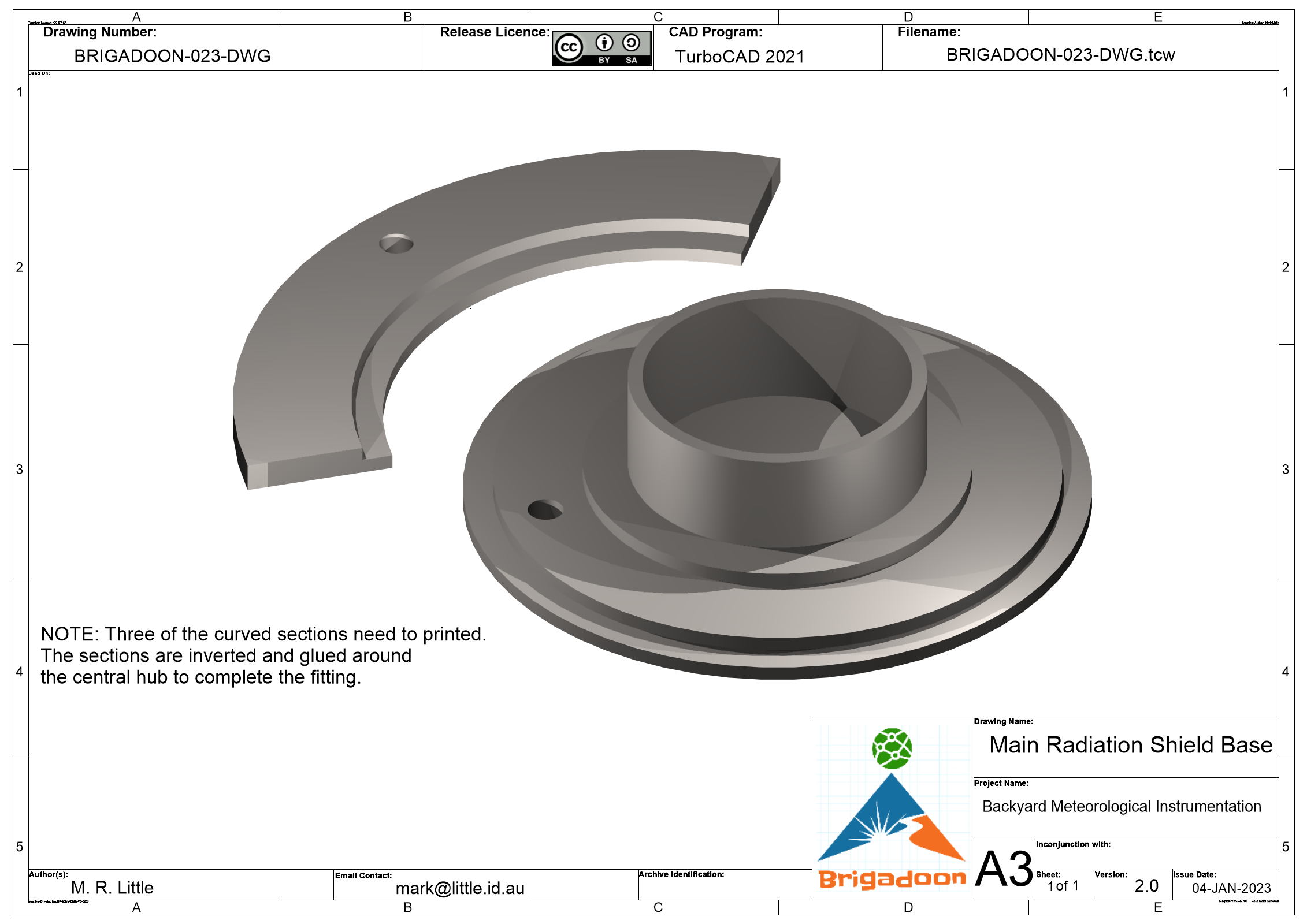
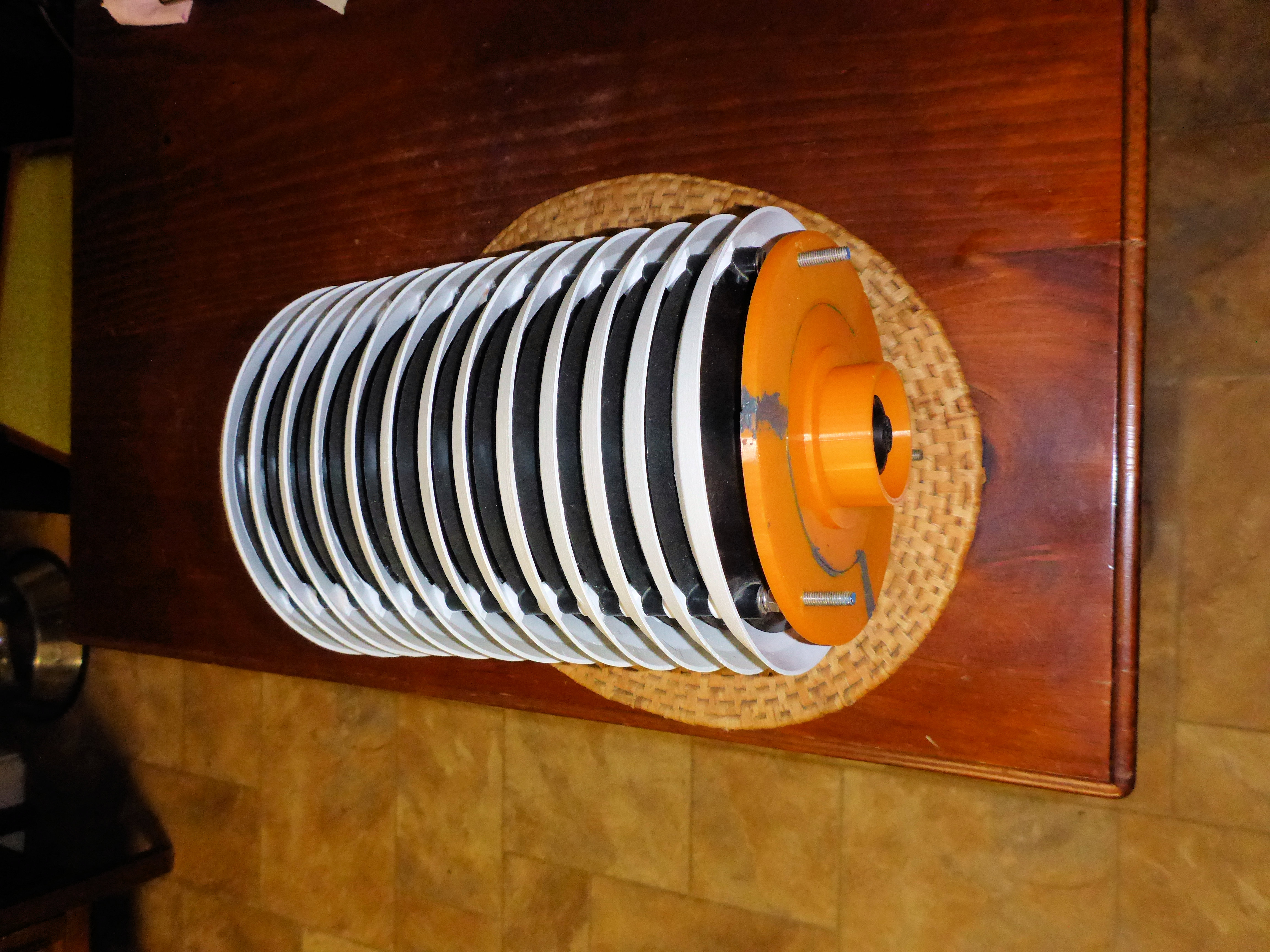
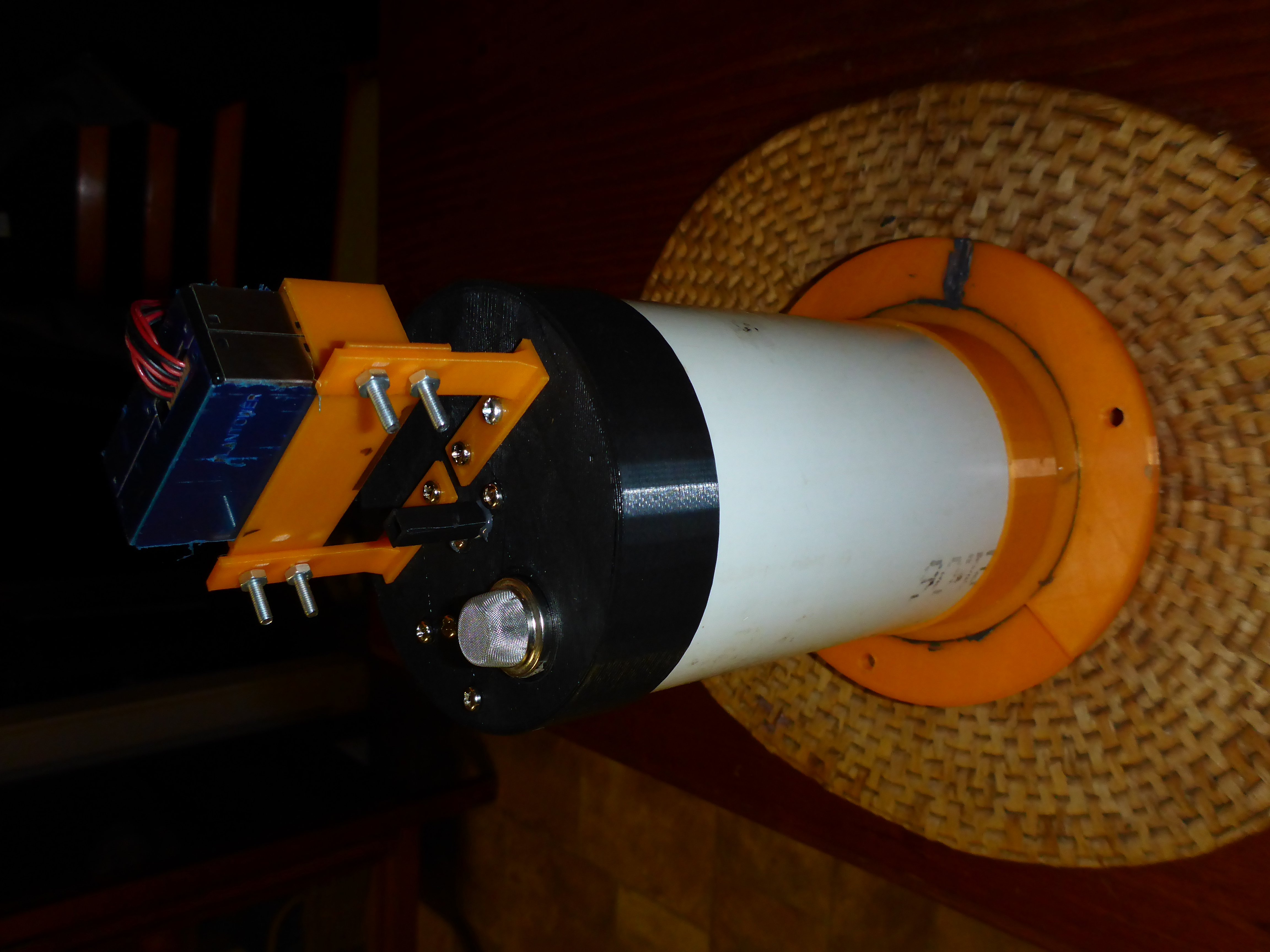
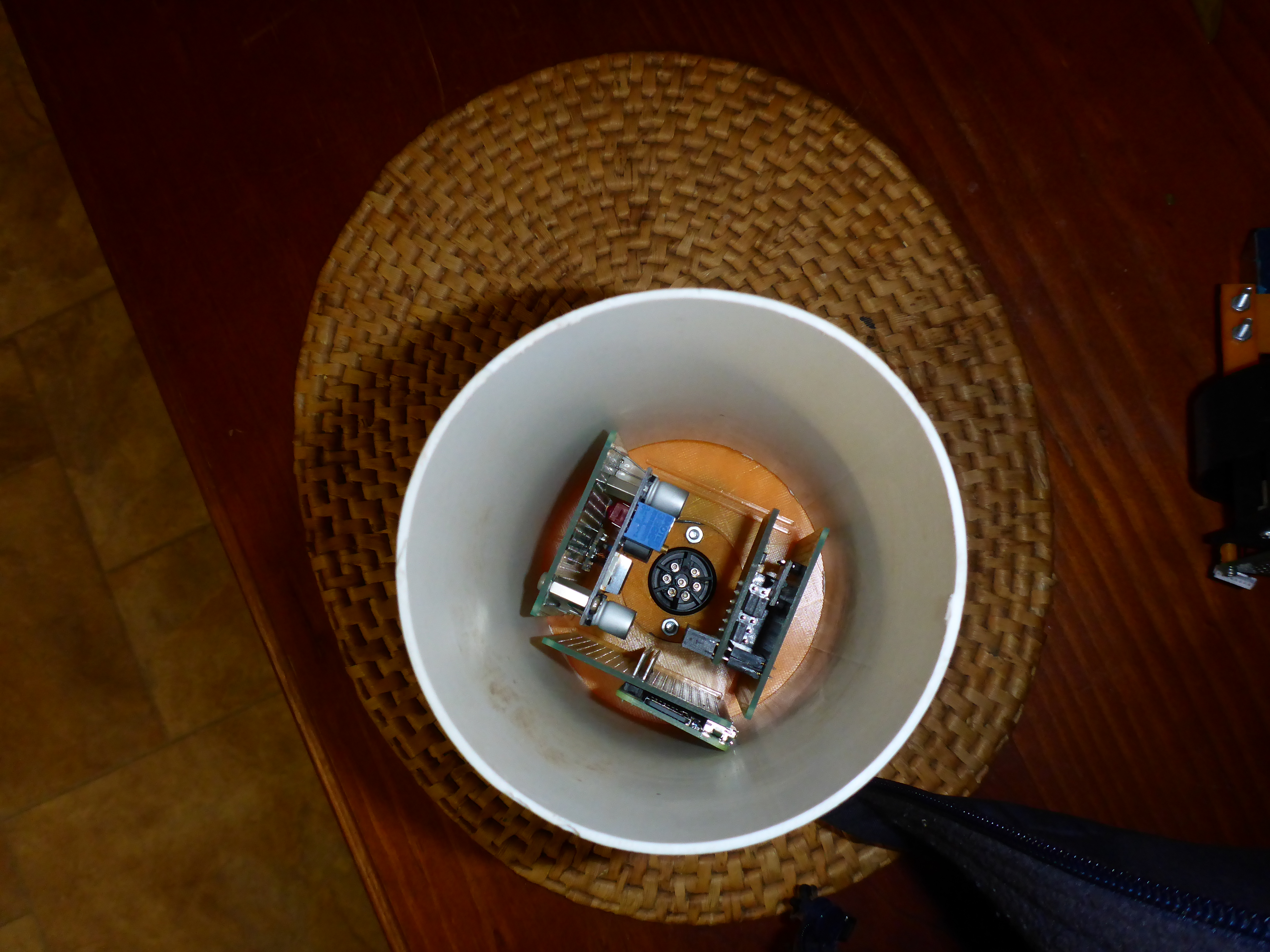
The air quality sensors will need to be mounted externally from the electronics box as the electronics box only has limited ventilation. To adequately expose the sensors, they will be placed in a ventilated solar radiation shield and mounted on one of the enclosure's poles or the pole behind the enclosure installation.
Mounted in the bordered area and away from the enclosure will be the sensors like the thermometer/relative humidity sensor, the ground temperature and soil moisture sensors.
Another edged area with a concrete base has been created inside that area and it will be where the box of electronics will be installed. The cables from the shed will come from the left of the image and along the upper edge of the outer border. and pass under the edge and come up next to the inner border.
The next step is to level the sensor area and sew it with grass. Bare dirt can heat up significantly and disturb sensors with radiated heat, although that wll happen anyway because of the metal fences. In reality, a grass surface makes it less likely that dirt will be tramped back into the house, creating a "domestic disturbance".
The air quality sensors will need to be mounted externally from the electronics box as the electronics box only has limited ventilation. To adequately expose the sensors, they will be placed in a ventilated solar radiation shield and mounted on one of the enclosure's poles or the pole behind the enclosure installation.
Mounted in the bordered area and away from the enclosure will be the sensors like the thermometer/relative humidity sensor, the ground temperature and soil moisture sensors.


