BRIGADOON

Backyard Meteorological Instrumentation

Power Supplies

Power Supply Overview

The initial sensor area is located near a shed which has mains power, and mains power will be used to power the sensor module. While it would be relatively simple to run a mains extension cord from inside the shed to the sensor box, it would be in contravention of the local electrical code unless installed by a licenced electrician. To overcome this issue, a D.C. power supply will be installed in the shed and low voltage D.C. cabling run out to the sensor box.

The higher the D.C. voltage, the lower the current that will need to be drawn, which will reduce the I2R power loss in the feeder cables. Looking at the readily available, reasonably priced power supplies, it has been decided that a +24V power supply will be used as the primary power supply. This could be directly used if it was later decided to power the second set of sensors using Power over Ethernet (PoE). Where practical, DC-DC regulators based on the LM2596 will be used to obtain the desired voltages for the electronic equipment, and it peak conversion efficiency is around +24V input.

Initially, the Raspberry Pi Zero W was selected as the main processing element and would communicate via Wi-Fi. However, since there was a world-wide shortage of Pi Zeros at the start of the project, it was decided to use a Raspberry Pi 4 for the first stage of the project. This provided the option of connecting to the sensor system via the gigabit Ethernet link in the shed. As a result, the power consumption of the project has increased.

Power System Analysis

Although the sensors to be installed are not completely defined (as this is an experimental setup), an initial set of sensors and support equipment is known as shown in the list below:
(1) Raspberry Pi 4 - 3.8W to 6.0W @ 5V (source);
(2)  PMS5003 Particle Concentration Sensor - 1mW to 0.5W @ 5V (source);
(3) MQ135 Gas Sensor - 0.8W when active  (source) @ 5V;
(4) HMP60 Temperature/Relative Humidity Sensor - 5mW to 20mW @12V (source);
(5) DS18B20 Temperature Sensor - <1mW to 7.5mW @ 5V (source);
(6) Capacitive Soil Moisture Sensor - 5mW to 10mW @ 5V (estimated);
(7) AS3935 Franklin Lightning Detector - 0.1mW (source);
(8) Met One Anemometer 014A - 0.0mW (source);
(9) Software Digital Receiver (SDR) - 1.5W to 2.0W @ 5V (source);
(10) ADS1115 Analogue to Digital Converter (ADC) - 10mW to 15mW @ 5V (source);
(11) Cooling Fan - 9.2W @ 24V(source).
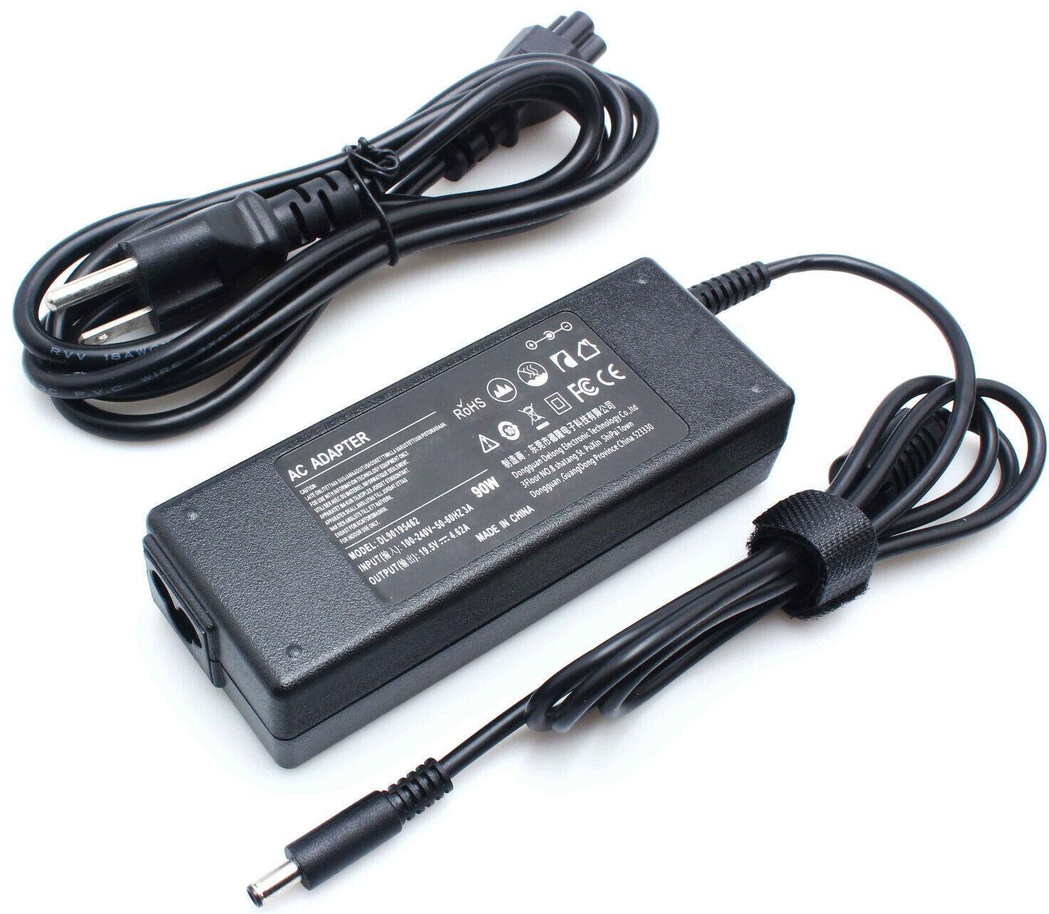
A draft analysis of the power requirements against the available power supply components is shown in this development drawing. The mains power supply unit is shown in the topmost image and the LM2596 step down converters using 24V input are shown in the photo below it.

The step down converter from +5V to +3.3V was originally designed to use the PTH04070W step down converter because a large number of these specialised converters were obtained at no cost. Because of its high conversion efficiency from +5V to 3.3V and the LM2596's lower efficiency converting from +24V to +3.3V, the two-step conversion efficiency from +24V to +3.3V is about the same as if the LM2596 was used to do a single step conversion. However, because the DIN Rail mounting system has been selected, it is more effective to make two DIN enclosures with two (2) LM2596 converters. In this way, a single spare can be used if either regulator enclosure fails.

Apart from the SDR, the Raspberry Pi 4 draws the largest current from the +5V supply. Although it operates at a lower current, it is suggested that the Raspberry Pi is powered from a 2.5A supply. If the Pi is later to be combines with the SDR, the peak current would be 2.8A, just within the limits of one of the LM2596 step down converters.

The second LM2596 5V down-converter is available to power other +5V sensors and circuitry. The third converter is used to supply the +3.3V

The final LM2596 step down regulator is set to output +12V volts. Currently only the HMP60 temperature/relative humidity sensor uses a +12V supply.

Since it is expected that the Raspberry Pi converter will dissipate the most heat and the +12V converter the least, these two units will be placed in the same enclose, while the +5V and the +3.3 regulators will be in the other enclosure to make the heat load as even as possible in the two enclosures.

There will also be a 24V fan that will be available to provide ventilation in the instrument box. This fan can draw 0.38A, but its operation will be controlled by the Raspberry Pi so that it will not consumer power when it is not needed. The LED lightning is only expected to be used occasionally and for short periods so it will it is not expected to be used if the fan is running.

Power System Block Diagram

DIN Rail Power Supplies

As indicated above, two (2) DC-DC Converters installed in a DIN rail enclosure. There are two enclosures, giving the four (4) supplies shown in the block diagram.

Because the converters use a potentiometer to adjust the output voltage, the construction of each unit is identical. The only difference between the units is that the indicator LEDs will have different limiting resistors based on the voltage output.

A 3D-printed chassis is required to mount the DC-DC converters in the DIN enclosure. The potentiometers visible from the front allow the output voltages to be adjusted without removing the unit from the DIN rail.

Licenced under Creative Commons Attribution Share Alike 4.0 International or better by Mark Little (2022 - 2023)