


SENSOR |
INTERFACE TYPE |
LOCATION |
DISCRIPTION |
SEN0290 Lightning Sensor |
I2C plus Interrupt |
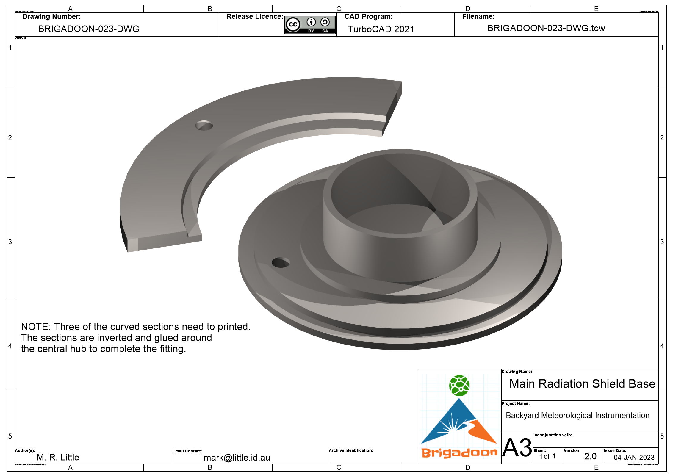
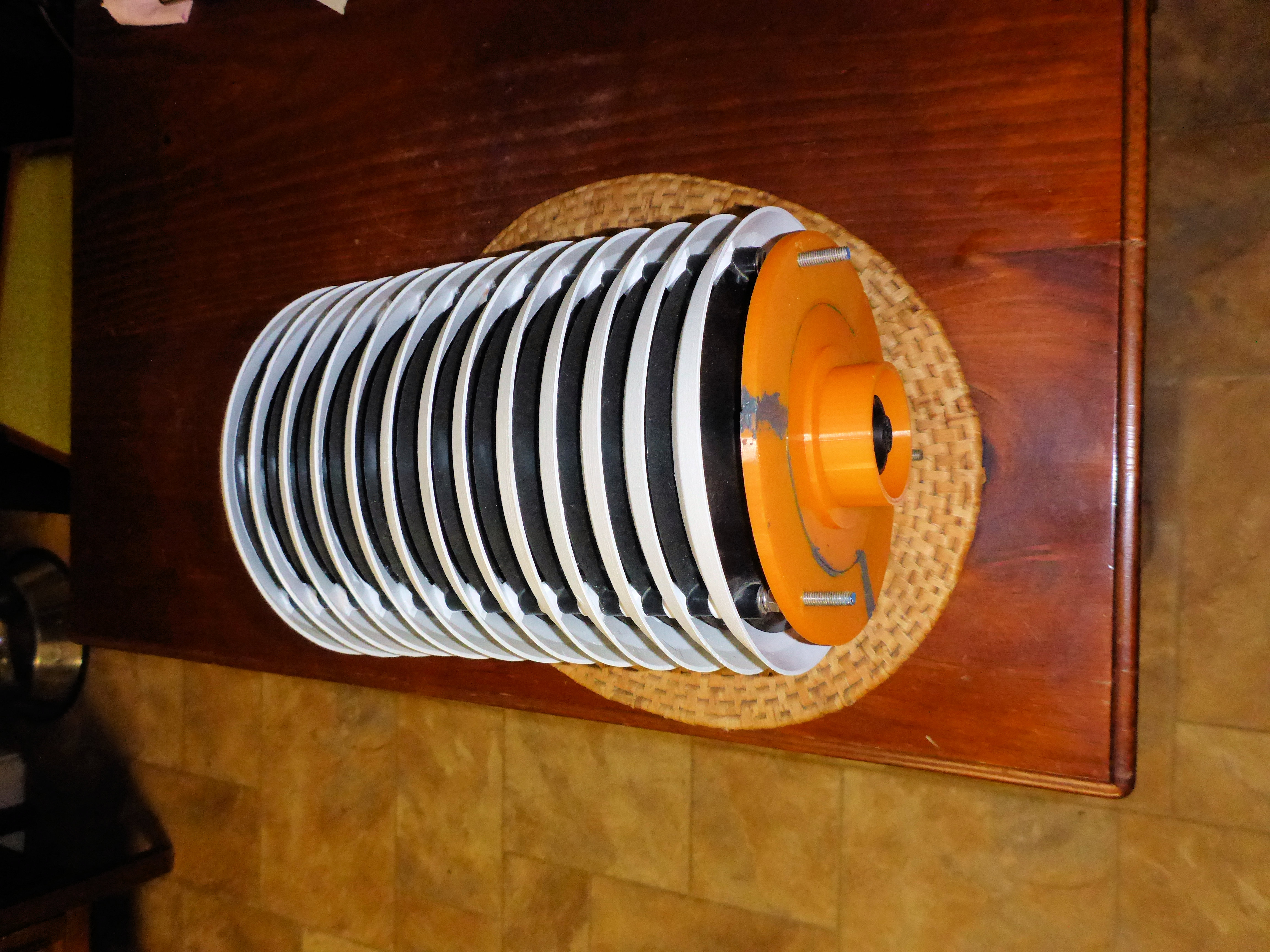
Main Radiation Shield on Pole or on top of the main enclosure (preferred) |
Sensor requires clear access to sky away from items creating electromagnetic interference. |
K324
|
Interrupt |
External Plastic Box |
Sensor element must not be shielded by metal. |
Anemometer |
Interrupt |
Vertical Pole |
This is a professional quality spinning cup anemometer that has been donated. It is not in an ideal position, so the wind speed will only reflect the micro-climate in the location. |
Rain Gauge |
Interrupt |
Vertical Pole or platform |
Should be clear of all obstructions, but this is unlikely to be the case, so results are not optimal. This tipping bucket comes from an old Personal Weather Station that uses a magnetic switch to detect buck tips. |
PMS5003 |
TTL Serial UART plus Control Pin |
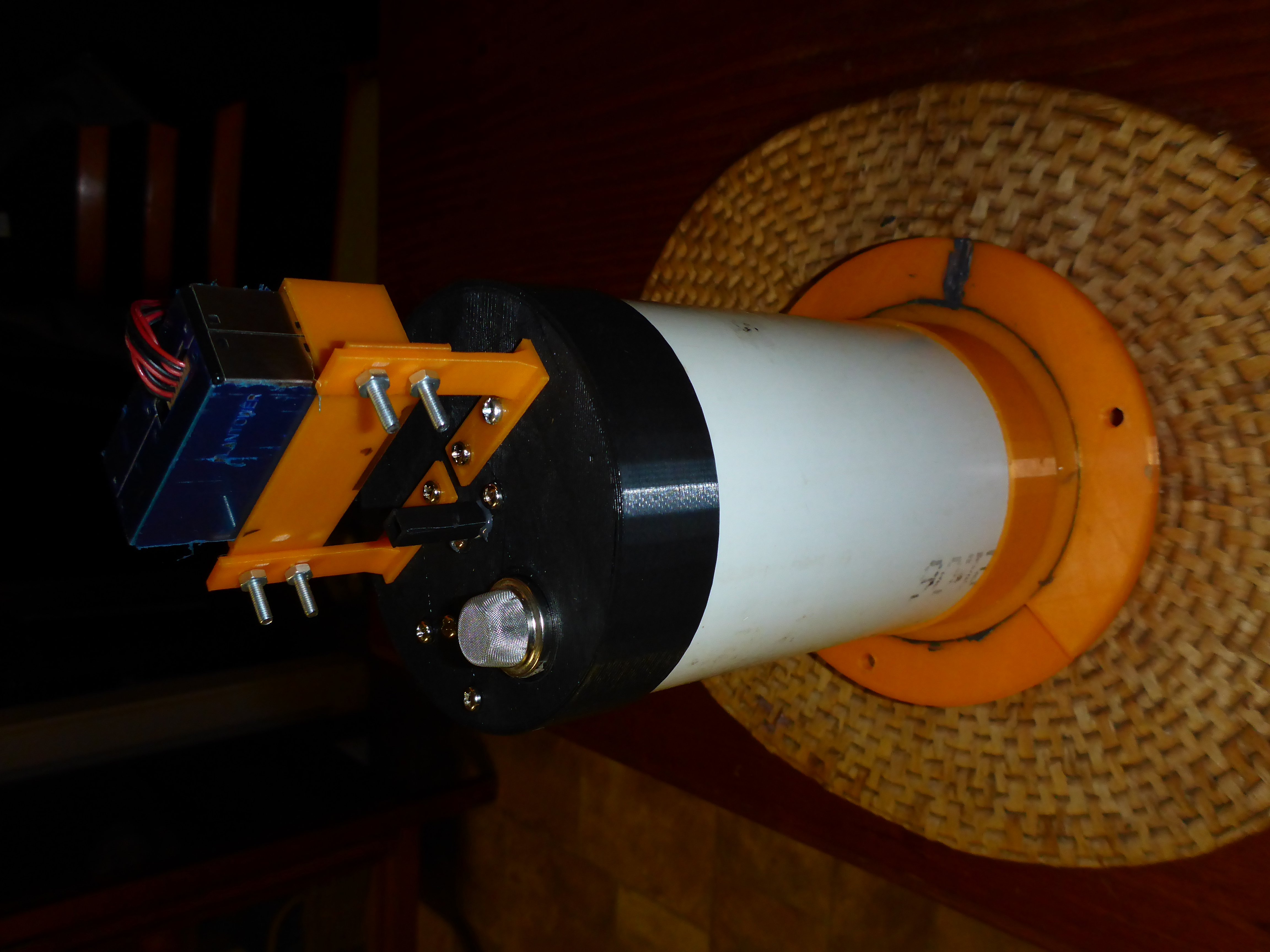
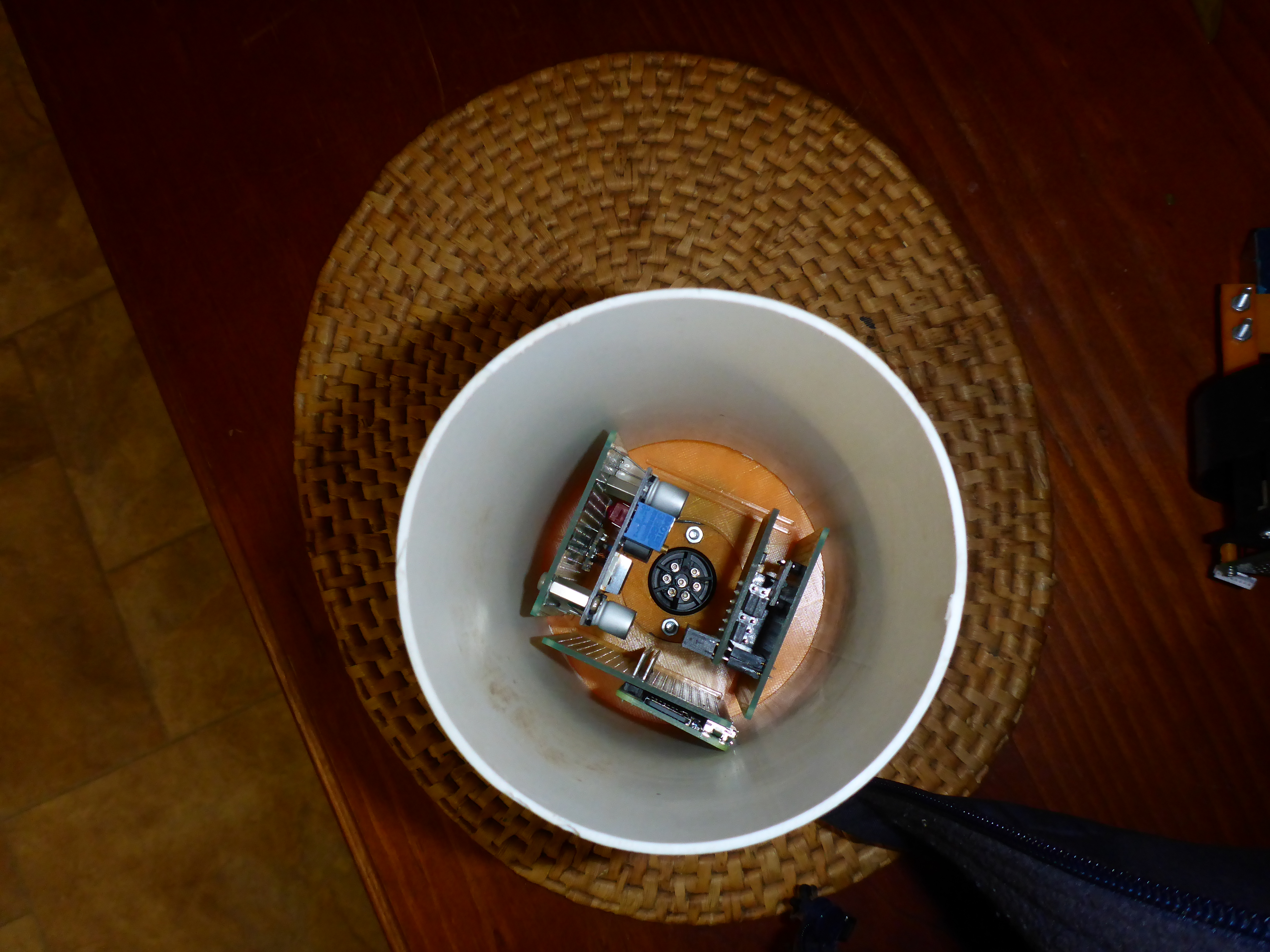
Main Radiation Shield |
Sensor requires free access to the local atmosphere. |
ADS1115 4 Channel 16-Bit ADC |
I2C |
Mounted in Main Enclosure |
This ADC is connected to the next four (4) sensors. |
MQ135 |
Analogue Signal |
Main Radiation Shield |
Sensor requires free access to the local atmosphere. |
SEN0193 Soil Moisture |
Analogue Signal (Plus Control Pin) |
Spiked into Ground |
Mounted in same box as Water Condensation (Rain Drop) Sensor. Not considered accurate. |
Water Condensation |
Analogue Signal |
Same box as Soil Moisture Sensor |
NOTE: This sensor will not initially connected as there will not be a free ADC channel available. If will be included if a second ADC is installed. |
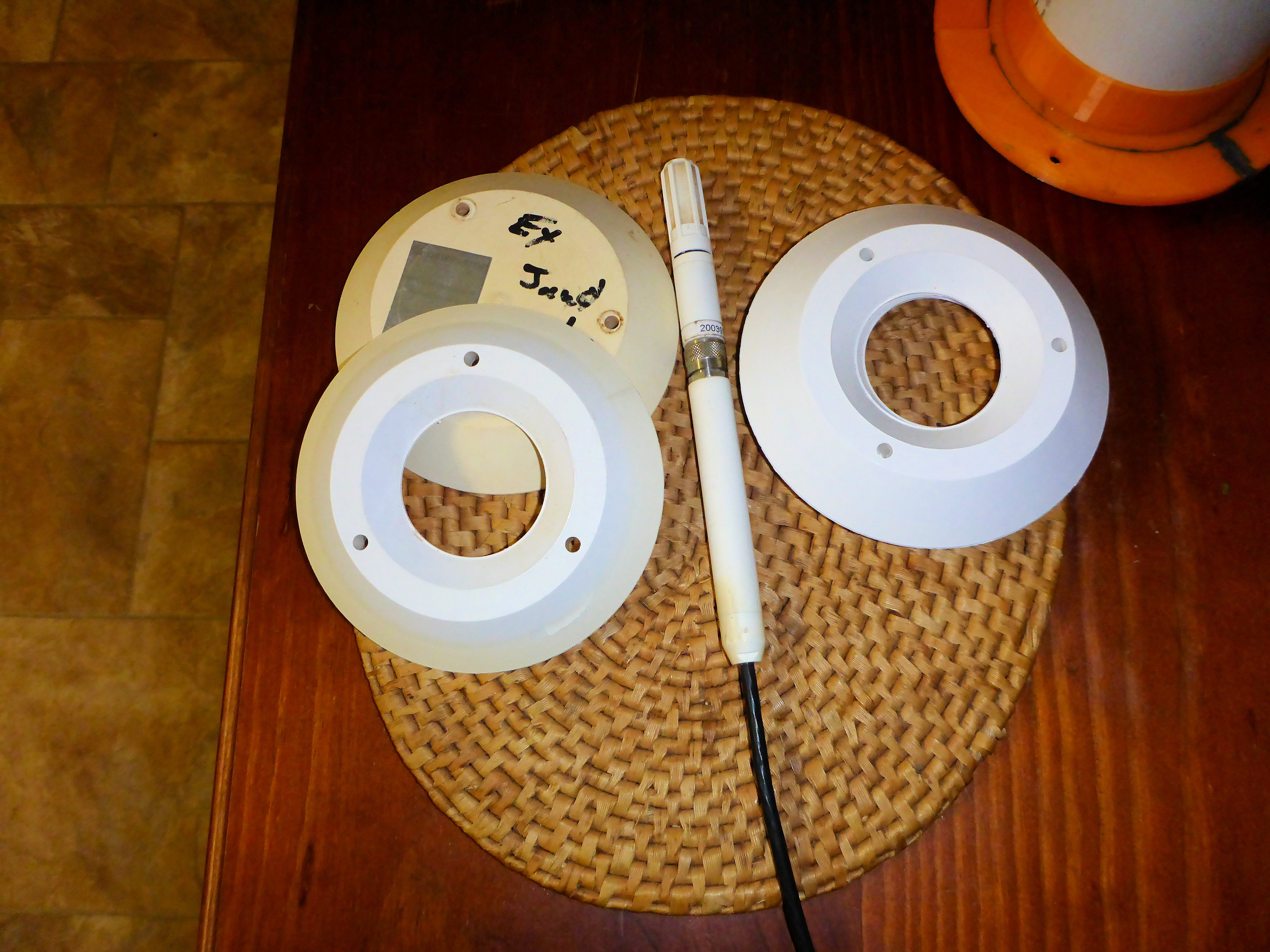
HMP60 |
Analogue Signal |
Secondary Radiation Shield |
Two (2) ADC Channels are required. High resolution channels are required for this project. |
DS18B20
|
I2C |
Underground Tube |
From previous experience five (5) of these thermometers is about the limit that an I2C controller can drive over a distance. |
BMP388 Barometric Pressure |
I2C |
Main Radiation Shield |
Must be kept out of the air flow from any cooling fans, etc. but still have good access to the outside atmosphere. |
Ultra-Violet Monitor |
I2C |
Main Radiation Shield |
Could be mounted on the top of the Main Radiation Shield. |
Infra-Red Temperature |
I2C |
Main Radiation Shield |
Could be mounted with ultra-violet sensor. |
Flight Aware Prostick Plus ADS-B Receiver
|
USB |
Main Enclosure - Receiver External Mount - Antenna |
|
CPU Temperature |
DIgital Output Pin |
Temperature sensor internal to the Raspberry Pi |
The Digital Output Pin is used to trigger external cooling fans to provide additional air flow across the Raspberry Pi's heatsinks. The temperature reading is available via the operating system software and the pin is automatically controlled by the Operating System. |

I2C Bus No. |
SDA GPIO PIN |
SCL GPIO PIN |
1 (Default Port) |
2 (Physical Pin 3)
|
3 (Physical Pin 5) |
2 |
-- |
--
|
3 |
4 |
5 |
4 |
8 |
9 |
5 |
12 |
13 |
6 |
22 |
23 |

Licenced under Creative Commons Attribution Share Alike 4.0 International or better by Mark Little (2022 - 2023)