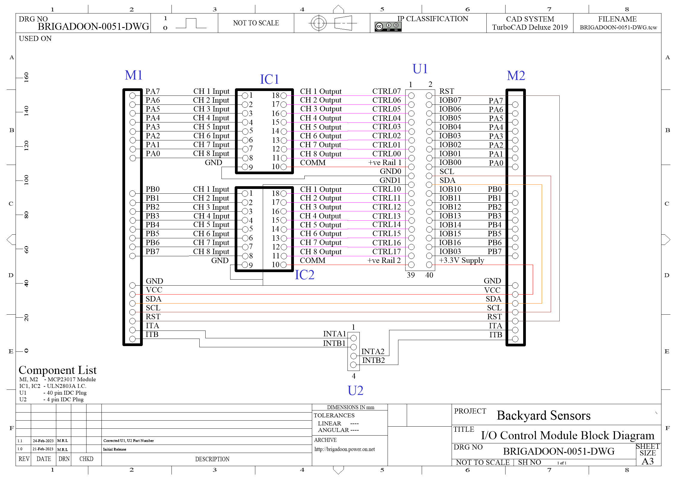
This module is designed to provide I/O management for the Raspberry Pi. Apart from providing more I/O cpntrol pins, it allows the Raspberry Pi to control higher power devices outside the current and voltage capabilities of the Raspberry Pi I/O pins.
The MCP23017 is capable of reading/writing 16-bit bits of data using the I2C interface.
An internal integrated power-on reset (POR) circuit resets to the device's default state. It has two programmable interrupt source outputs that can be used individually, or combined as one signal. The polarity toggle register configures the GPIO input polarity and can also be configured as an output. It can be set to use a pull-up resistor, and the IO configured as an input or output. The IO port has strong driving capability, and the current sinking and sourcing current can reach 25mA.
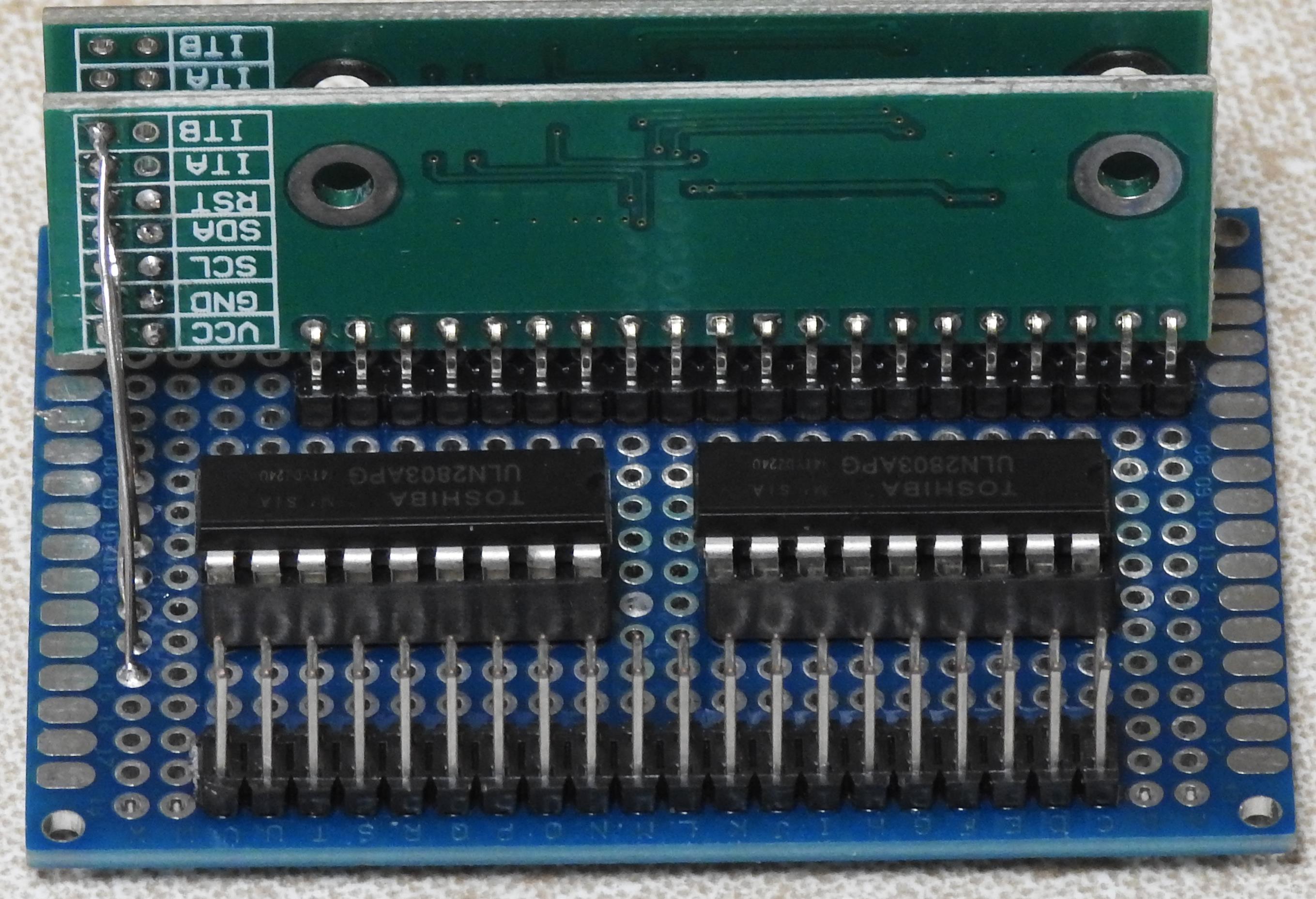
The I/O Module is built on a 6cm x 4cm prototype board, with two (2) MCP23017 modules mounted vertically on the board. There are two (2) ULN2803a open collector Darlington arrays. One array has its flyback diodes connected to the +5V supply. This MUST be connected to the +5V rail as this also supplies power to the MCP23017 chips.
The other array can be connected to the +5V, +12V or +24V supplies to match the supply to inductive loads.
The open collector outputs may be paralleled to increase the load current that may be switched, as long as the software controls the corresponding input bit simultaneously. Each output can switch up to 350mA, while the total current for all channels should not exceed 2A.
The electronics of this device are constructed on a 5cm x 7cm prototype board. Two (2) 18-pin and two (2) 28-pin IC (Integrated Circuit) sockets are soldered onto the board, along with a 40-pin male IDC connecter that will ultimately connect to the same type of terminal strip as the Raspberry Pi uses.
Because two (2) MCP23017 units are being used on the same bus, the address on one of the units must be changed by altering the jumper on the A0 address line. The unit where the address is not altered will have the address 20, while the one with the change to the A0 address line will be 21.
To confirm this is the case, connect the +3.3V supply and the Earth to pin 40 and 21 respectively on the I/O Module's IDC connector. NOTE Connecting the module's supply to the +5V supply will damage the Raspberry Pi in a most expensive manner.
The SCL and SDA lines from the Raspberry Pi are then connected to the module's SCL and SDA pins, and the system power up. When you log into the Raspberry Pi enter the following command and confirm that result matches the example below.
mark@ares:~ $ i2cdetect -y 1
0 1 2 3 4 5 6 7 8 9 a b c d e f
00: -- -- -- -- -- -- -- --
10: -- -- -- -- -- -- -- -- -- -- -- -- -- -- -- --
20: 20 21 -- -- -- -- -- -- -- -- -- -- -- -- -- --
30: -- -- -- -- -- -- -- -- -- -- -- -- -- -- -- --
40: -- -- -- -- -- -- -- -- -- -- -- -- -- -- -- --
50: -- -- -- -- -- -- -- -- -- -- -- -- -- -- -- --
60: -- -- -- -- -- -- -- -- -- -- -- -- -- -- -- --
70: -- -- -- -- -- -- -- --
When you are wiring up the terminal strip that is connected to the I/O module, to copy this project, the +5V supply is connected to Pin 15, and the Earth of the +5V supply is connected to Pin 17. Pins 1 and 3 are connected to the Switched Earth pins of the Raspberry Pi's fans, so that they can be controlled by the Raspberry Pi. If this module is used to switch units connected to the +12V supply and the loads are likely to be inductive, the +12V supply should be connected to