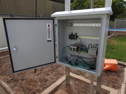
The Main equipment shelter was originally designed for electric gate control. The box has been bolted to two (2) 50mm x 50mm x 1800mm fence posts using 12mm bolts. The posts are being being set into the ground to a depth of 400mm and the base reinforced with concrete. Once concrete is poured in, it will be about a week before the concrete reaches its maximum strength, although this not considered to be critical, since there should be minimal issues with wind resistance as it is mounted near the corner of two tall fences with trees and structures on the other side of the fences.
The image below shows the initial development installation. The Raspberry Pi is connect to the home LAN and can be controlled using SSH or VNC from anywhere on the network. Cable forming will be carried out after the remaining hardware is made and installed.
There are four (4) DIN rails in the enclosure. The bottom three (3) sections of rail are recovered items and are not the correct width for this project. If space becomes an issue the second and third rails from the bottom will be replaced with wider sections, although due to the external cables which terminate at the left had side of these rails, the space gained will be limited on that side.


