
Backyard Meteorological Instrumentation

Hardware System Overview
DIN Rail Mounting
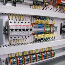
As this project will be permanent installation, the hardware will be installed in a more permanent configuration that the home projects usually are. The Raspberry Pi, power supplies, sensors and terminal strips will be mounted on DIN rails inside an equipment enclosure concreted into position in the back yard.
The DIN Rail is simply a piece of punched steel in the shape similar to a "U" with wings. Various enclosures, connectors and assorted mounting hardware to allow items not designed for the DIN rail to be mounted.
By mounting lengths of the DIN rail in an enclosure, the configuration of the hardware can be updated or replaces simply by unclipping the items from the DIN Rail along with removing the interconnections. In most cases, no additional holes need to be drilled to mount new, or shift existing hardware.
The disadvantage of this system is that it is generally ore expensive than just installing equipment boxes directly to the enclosure, but this extra cost does provide a cheaper method of changing the hardware around.
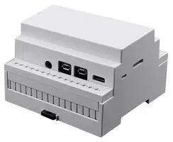
The Raspberry Pi 4 DIN Rail enclosure is designed to hold the Pi using a clip-in design. All cut-outs are provided for the I/O connectors and the memory card slot. The board in mounted upside down to allow a Pi Hat to be installed.
WARNING: I have had to enlarge the slot for the SD card to prevent the card being under tension from the case, This tension ultimately caused a card to SNAP AND FAIL!!
WARNING: I have had to enlarge the slot for the SD card to prevent the card being under tension from the case, This tension ultimately caused a card to SNAP AND FAIL!!
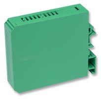
There is a wide range of DIN Rail enclosures that are available to hold sensors and power supplies. These enclosures will be selected based on the dimensions of the item being installed. If required, 3D-printed adaptors will be made.
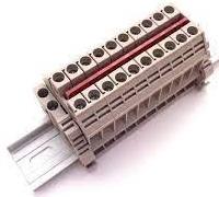
A wide range of individual terminals and terminal blocks for wires of different sizes are available for mounting on the DIN Rail.
The DIN Rail mounting system allows terminals to be easily installed and even altered in the future without major modifications to the mounting hardware. Such changes are practical in the field, if there is sufficent space for the new configuration.
The DIN Rail mounting system allows terminals to be easily installed and even altered in the future without major modifications to the mounting hardware. Such changes are practical in the field, if there is sufficent space for the new configuration.
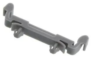
Various clips are available which can be attached to other enclosures to make them DIN Rail compatible.
For this project, the Software Defined Radio (SDR) is attached in these clips using Nano Tape.
For this project, the Software Defined Radio (SDR) is attached in these clips using Nano Tape.
Main Solar Radiation Shield
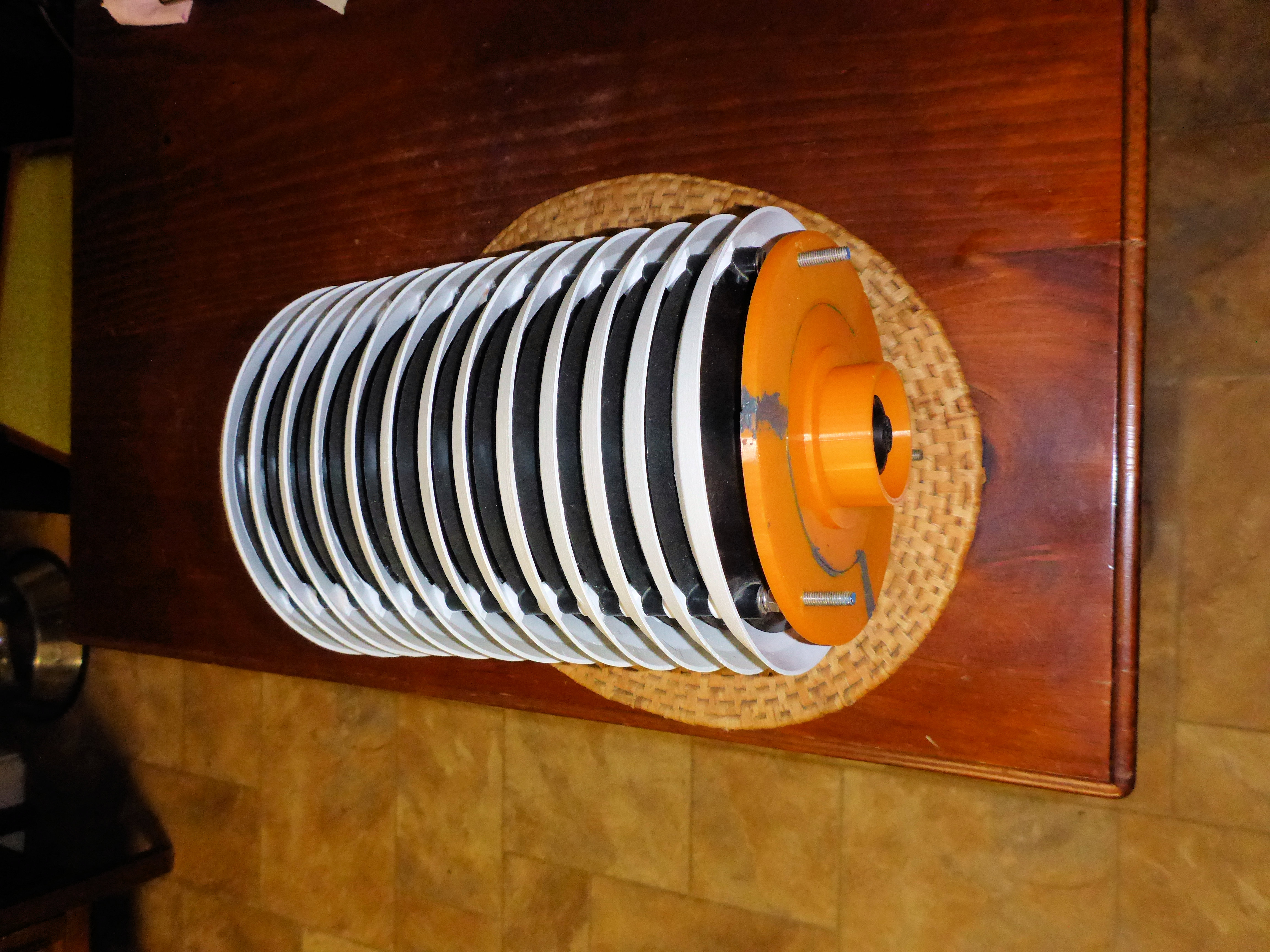
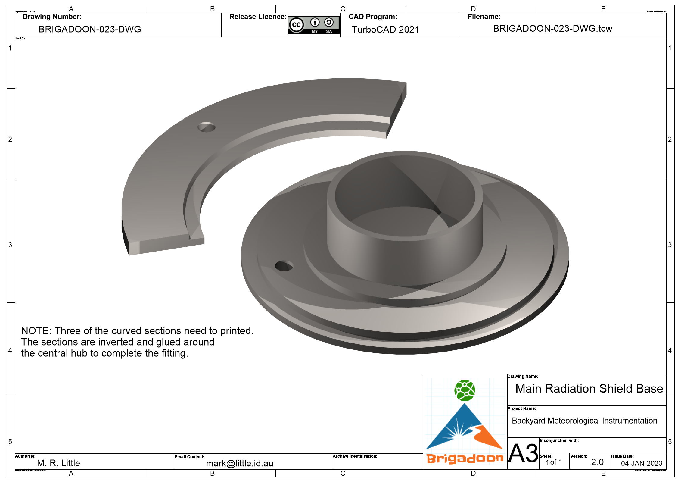
The main radiation shield is based on the Campbell Scientific RAD06,10,14 & Met20/21 Unaspirated Radiation Shields, but with a custom base that replaced the instrument ts that were normally attached to this shield. The base, shown in orange in the image of the left was printed on a small 3D Printer (Snapmaker Original).
Click on the image on the right to see a larger image and if you can read TurboCAD files, here is the CAD File.
Click on the image on the right to see a larger image and if you can read TurboCAD files, here is the CAD File.
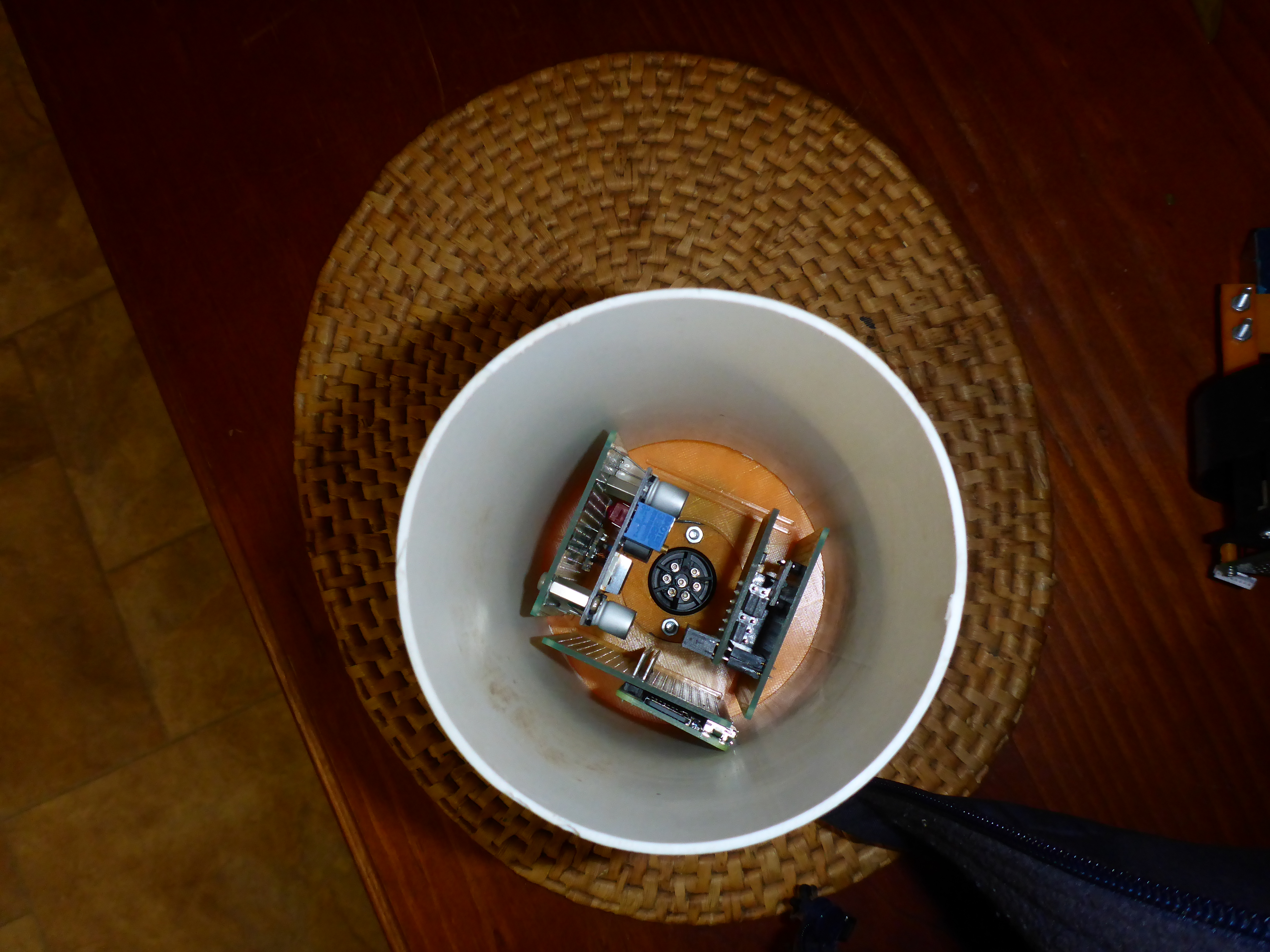
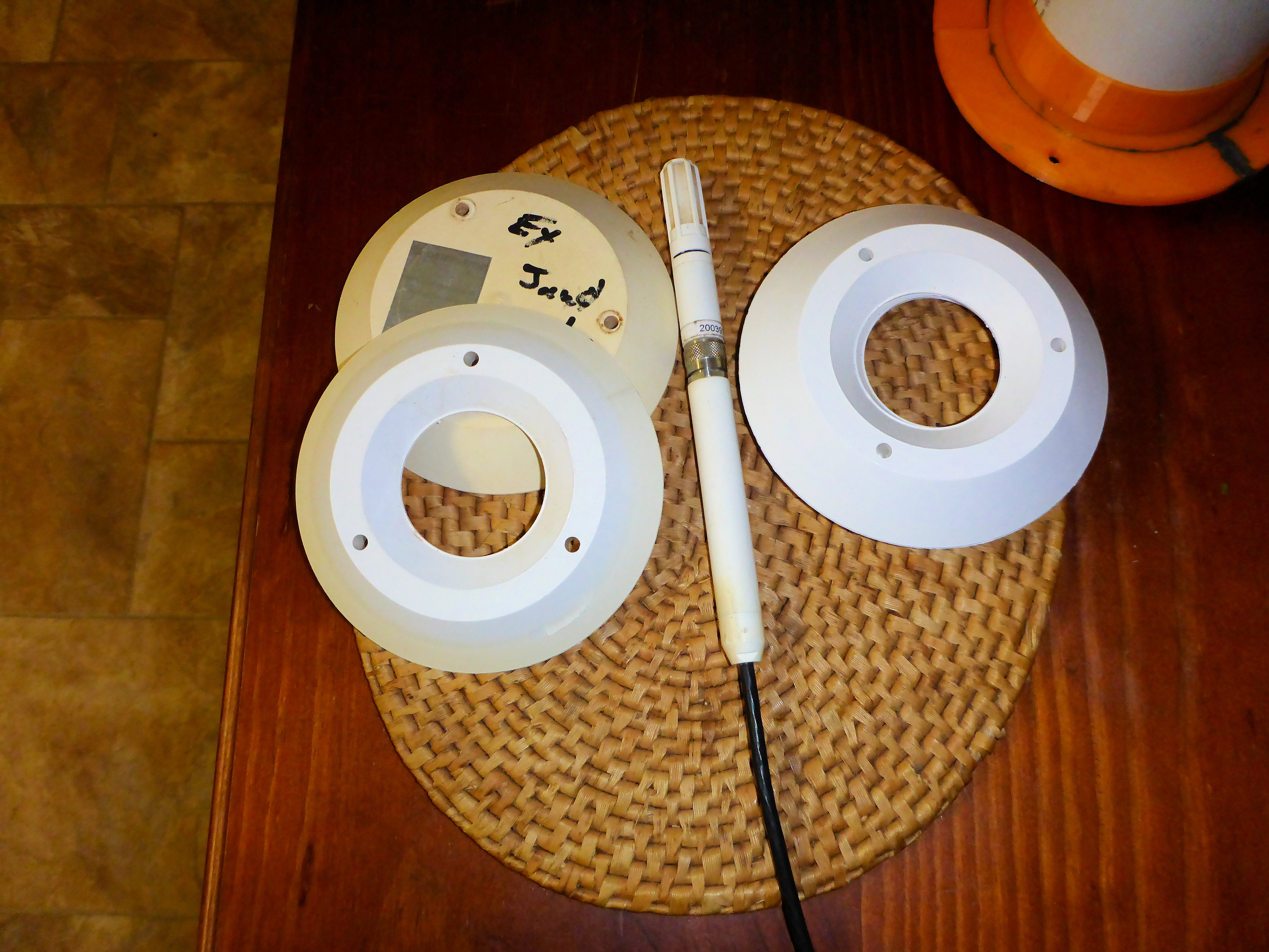
The reverse side of the base shown above is used to hold adaptors for sensors. In this example, the ring shown in the image on left is small enough to fit into the body of the radiation shield, but large enough to hold a piece of plastic downpipe.
Double clicking on the right image shows that there are grooves on the bottom which provide a friction fit for up to four (4) small prototype circuit boards.
The connector that is visible at the bottom is a weatherproof seven (7) pin connector that is used to supply power and control signals.
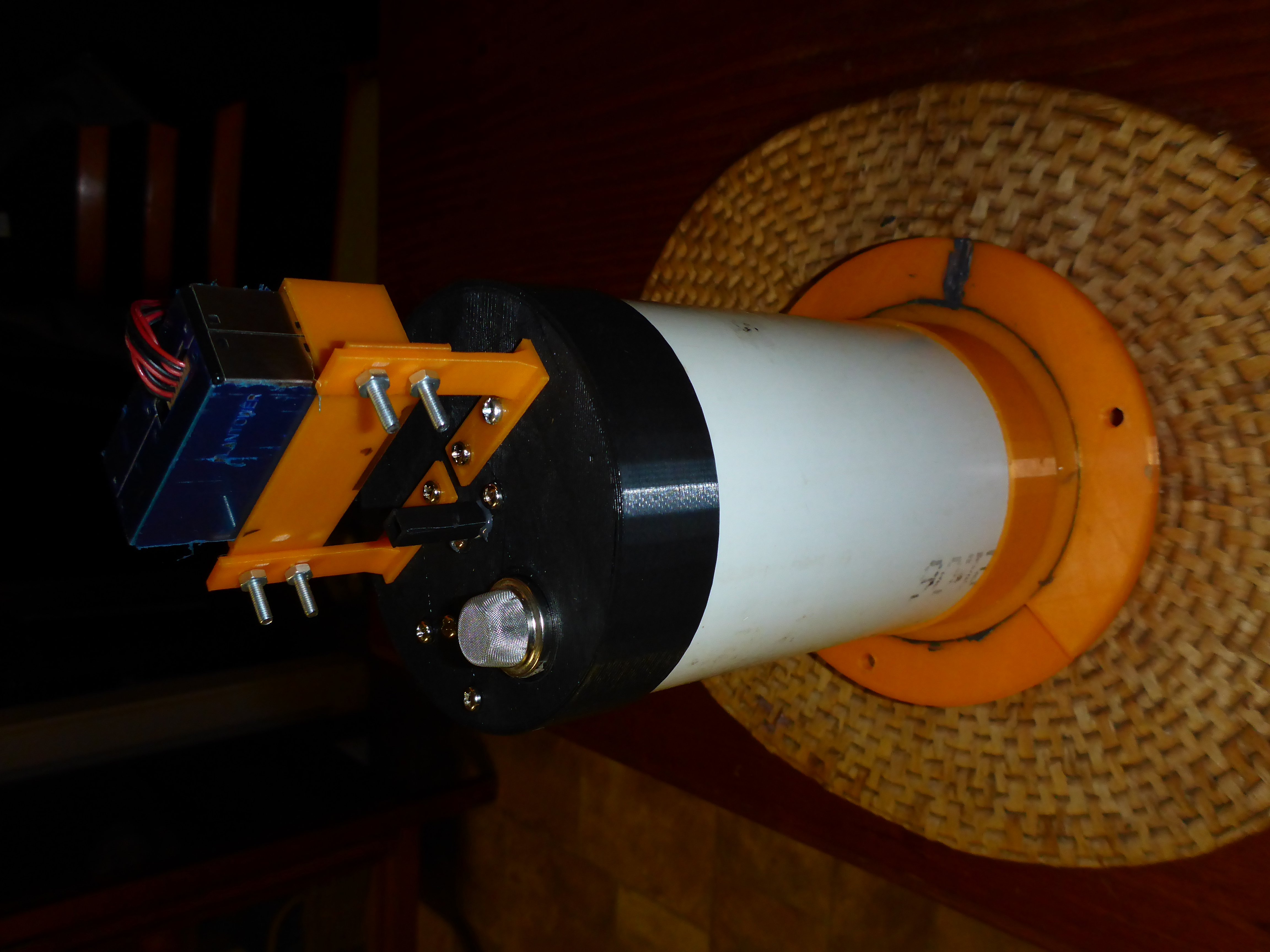
Look at the photo on the left, the fitting on top of the section of downpipe is a fitting that is used to hold the sensors that need to be exposed to the atmospheric air flow though the shield. A barometer is mounted inside the fitting which has a small tube that protects the barometric sensor from any particles in the air, but allows the pressure to equalise inside the fitting.
Double clicking on the right image shows that there are grooves on the bottom which provide a friction fit for up to four (4) small prototype circuit boards.
The connector that is visible at the bottom is a weatherproof seven (7) pin connector that is used to supply power and control signals.
Look at the photo on the left, the fitting on top of the section of downpipe is a fitting that is used to hold the sensors that need to be exposed to the atmospheric air flow though the shield. A barometer is mounted inside the fitting which has a small tube that protects the barometric sensor from any particles in the air, but allows the pressure to equalise inside the fitting.
Secondary Solar Radiation Shields
The secondary radiation shields, of which there are two (2), are much smaller than the primary radiation shield and do not have the black internal spacers like the main shield. In this project one of these shields will be used to house the relative humidity/temperature sensor. The restricted internal cavity, no other sensors will be installed in this radiation shield. This sensor being installed in this shield is powered by +12V and
As yet, a 3D-printed mounting plate for the sensor has not been designed and printed.
As yet, a 3D-printed mounting plate for the sensor has not been designed and printed.
Intersite Cabling
There are three (3) sites involved in this installation: The new equipment enclosure, the garden shed and the house and there is cabling between these locations.
The main cabling is between the new equipment enclosure and the garden shed. The cabling consists of two (2) CAT6 Ethernet cables, a +24V power cable and a six (6) wire status cable. The garden shed has mains power and this is where the +24V power supply that powers the new enclosure is located. It also has an eight port Ethernet switch that is currently used for the Sky Camera's connection to the main Linux server in the house. The Ethernet cables to the new enclosure will join the local LAN network at this point.
If required later, additional power can be provided over the Ethernet cables using PoE (Power Over Ethernet) adapters. The passive PoE adaptors available are capable of providing an additional 15W of power for each Ethernet cable. It is likely that another CCTV camera may be mounted on the enclosure and that its power will be provided by PoE.
At this stage, there is not a defined purpose for the status cable, but with six (6) wires in the cable, it is possible to use it for communication with a microcontroller like an Arduino or a Pico. It could even just be used for a remote status display panel. As there is a similar cable from the garden shed to the back deck of the house, the status of this system could be displayed on the back deck using just LEDs or an Arduino or Pico with a small display.
